- Published on
AI-supported woodworking: Building an up-and-over tool chest with a four-bar hinge
- Authors
- Name
- Markus Palme
A carpenter working in my house had this very cool toolbox: Closed, it's a carry box with a handle on top. When you open it, the front part swings up over the handle and comes down flat on top of the body. The chest becomes an upright cabinet twice as tall, with one continuous slanted front. I wanted one for myself and quickly identified it as the ECE Montagebox at Fine-Tools but the price was prohibitive - clearly a product targeted at professional tradesmen.
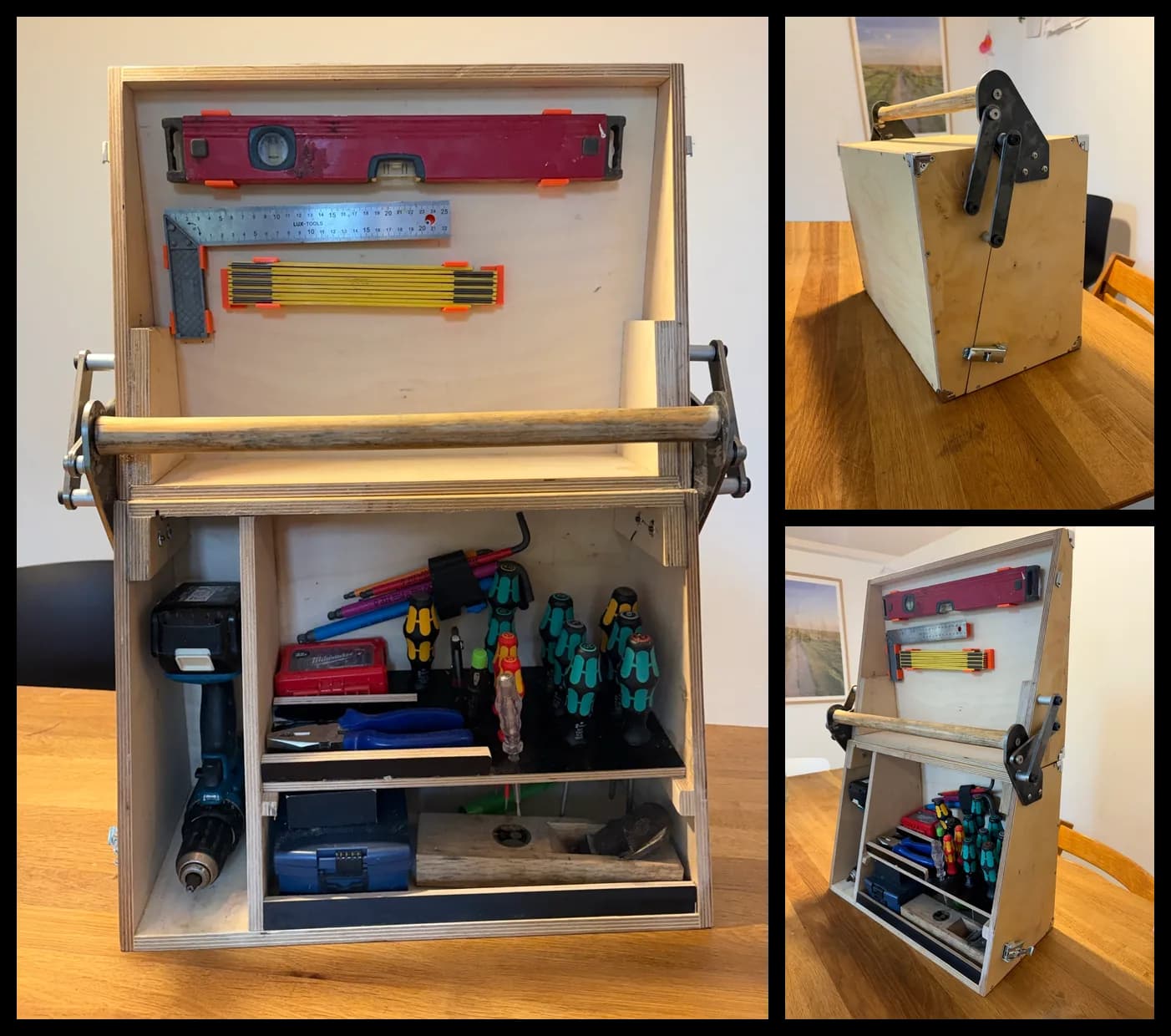
So I considered building this myself but never found the time to reverse engineer the hinge. But when I saw the demos of gpt-6-astra doing advanced 3D design, I decided to give it a go with AI assistance. Claude Opus 5.5 was the model of choice and what can I say: it delivered. It started by simulating the hinge in Python and continued with a full 3D model, parts lists and drawings. This was the moment I decided to go all in with the AI approach and let it handle the procurement of parts. It happily added the required screws and metal inserts to my Amazon cart, generated DXF files for the steel parts which had to be laser cut, compared prices on those and advised which steel to use. The wooden parts were next: it ordered them pre-cut and gave each piece a label in line with the drawings.
Over the next few days, packages started showing up at my doorstep and the excitement grew: Would everything fit together?
I had to cut the diagonals and the angled pieces myself; the online store didn't offer these options. With a track saw, this was quick work. In hindsight, I think it would have been easier to assemble a full box instead of the two halves and just cut it apart.
Everything came together nicely, except for one screw-up that was entirely my fault: I cut one of the diagonals the wrong way and had to replace that wood panel. Luckily, the local hardware store had the plywood in the right thickness. All in all, the build cost around 220 EUR.
Lessons learned
This build turned out to be a fascinating lesson, and here's what I took away from it (because I used AI, not despite it):
- To construct the hinge, you can use a procedure called three-position Burmester synthesis. This video shows the principle.
- I had never used shoulder screws and threaded inserts in my woodworking projects before. Another thing added to my toolbox (pun intended).
- Claude handled this surprisingly well, even in a continued conversation with multiple compactions. In total, about 28 million tokens were used.
Having the essentials in one toolbox has turned out to be a huge help for the odd jobs around the house. Previously, I'd head out to the shed for the tool I needed, only to trudge back a second time for something else, then a third time, and so on.
Build guide
Below you'll find all the details and files to build your own version of this box.
1. At a glance
| Spec | Value |
|---|---|
| Body, closed | 486 × 350 × 268 mm (W × H × D) |
| Width over links / screw heads | approx. 544 / 557 mm |
| Height with handle | approx. 423 mm |
| Height, open | 701 mm |
| Materials | 12 mm birch plywood, 5 mm laser-cut steel, Ø30 beech dowel |
| Parting line | 15° from vertical |
| Lid (front wedge) | 40 mm deep at the bottom, 133.8 mm at the top |
| Body (rear) | 227.5 mm deep at the bottom, 133.7 mm at the top |
| Gap between lid and body | 0.5 mm |
Simulate the hinge yourself
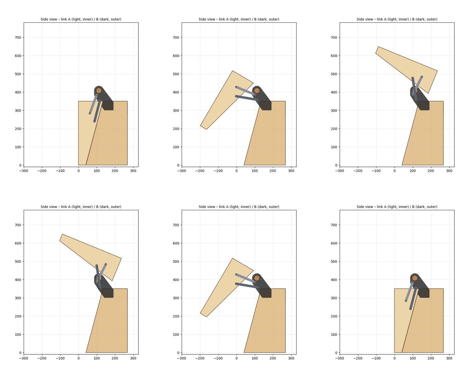
The motion was checked with a small Python simulator: hinge_sim.py. It needs only numpy and matplotlib.
- It drives link A from the closed to the open angle.
- It solves link B by circle intersection, staying on the same assembly branch.
- It moves the lid outline through every pose and checks it against the body and the handle.
For the final design it reports:
link A length            109.6 mm
link B length            121.5 mm
open-pose error           0.03 mm  (lid flat on body)
max forward swing        220.1 mm  (ahead of the front)
max behind the back       10.0 mm
min clearance handle      16.4 mm
min transmission angle    44.4 °
collision with body    no
Run python hinge_sim.py --gif to also get the side-view sequence and an animation.
You can change the pivot coordinates at the top of the file to try your own geometry. The script also contains two synthesis helpers:
project_on_bisector()snaps a fixed pivot onto the line where the link has the same length closed and open. That makes it a valid two-position design.circumcenter()does the classic three-position (Burmester) synthesis.
2. Materials and sourcing
Plywood
All panels are 12 mm birch plywood. The reinforcements behind the pivots are 18–21 mm thick; anything in that range should work. I ordered everything pre-cut from an online cutting service (https://www.plattenzuschnitt24.de/) and did the angled cuts myself with a track saw.
Lid (front wedge, 485 wide)
| Pos | Part | Qty | Finished size |
|---|---|---|---|
| D1 | Side panel, trapezoid 40 / 133.8 deep | 2 | 350 high |
| D2 | Front | 1 | 461 × 350 |
| D3 | Top, rear edge 15° | 1 | 461 × 118.6 / 121.8 |
| D4 | Bottom, rear edge 15° | 1 | 461 × 28.0 / 31.2 |
| D5 | Pivot reinforcement, 18–21 mm | 2 | 119 × 123, slanted |
Body (rear trapezoid, 486 wide)
| Pos | Part | Qty | Finished size |
|---|---|---|---|
| K1 | Side panel, trapezoid 227.5 / 133.7 deep | 2 | 350 high |
| K2 | Back | 1 | 462 × 350 |
| K3 | Bottom, front edge 15° | 1 | 462 × 215.5 / 212.3 |
| K4 | Top, front edge 15° | 1 | 462 × 124.9 / 121.7 |
| K5 | Handle plate reinforcement, 18–21 mm | 2 | 138 × 48, slanted |
Other
| Pos | Part | Qty | Size |
|---|---|---|---|
| G1 | Handle, beech dowel Ø30 | 1 | 486 long |
Where two widths are given, they are the narrow and wide face of the 15° bevel.
Steel (laser cut, 5 mm)
Order two of each from any online laser-cutting service (I used https://laserteile-online.eu/). Mild steel such as S235 is fine.
Hardware
- 8 shoulder screws ISO 7379, shoulder Ø8, thread M6: 2 each in lengths 10 / 16 / 25 / 30
- Aluminium tube 14 × 2 (ID 10), approx. 15 cm, for the spacers, plus a few thin M8 washers for shimming
- 6 threaded inserts M6 × 20: 4 for the lid pivots and 2 for the handle ends
- 2 countersunk screws M6 × 25 (DIN 7991) for the handle
- Handle plate mounting (per chest, with 20–21 mm reinforcements):
- 4 × M5 × 40 button head with 4 M5 T-nuts
- 2 × M5 × 45 with 2 nuts (self-locking) and 2 small washers (DIN 433)
- With 18 mm reinforcements use M5 × 35 and M5 × 40 instead.
- About 40 wood screws 3.5 × 30 and wood glue (D3)
- 2 draw latches at the lower sides, holding the lid to the body. I chose Ganter GN 831 in stainless.
- Loctite 243
3. Drawings, templates and CAD
Dimensioned drawings of all wood parts (PDF):
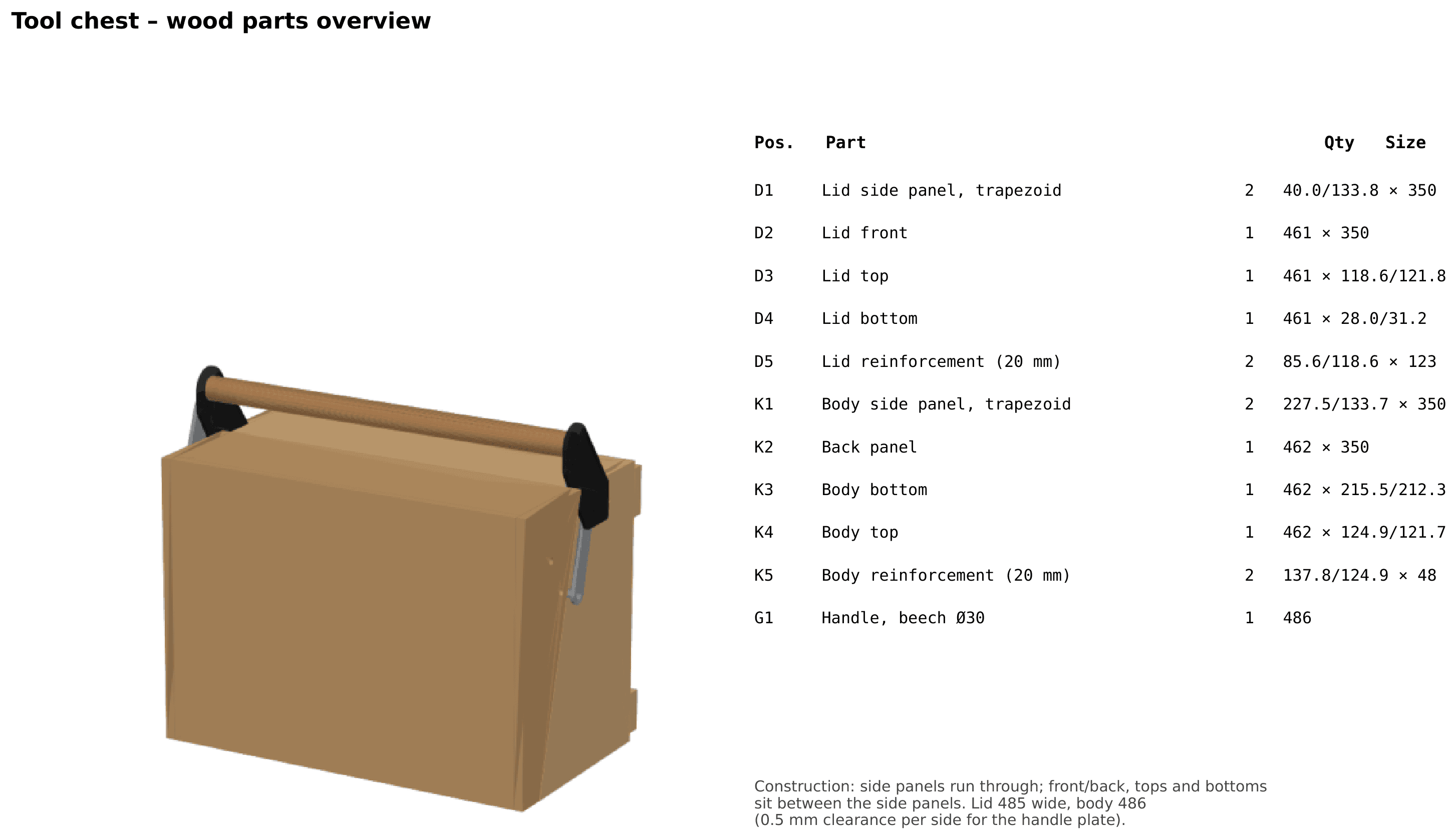
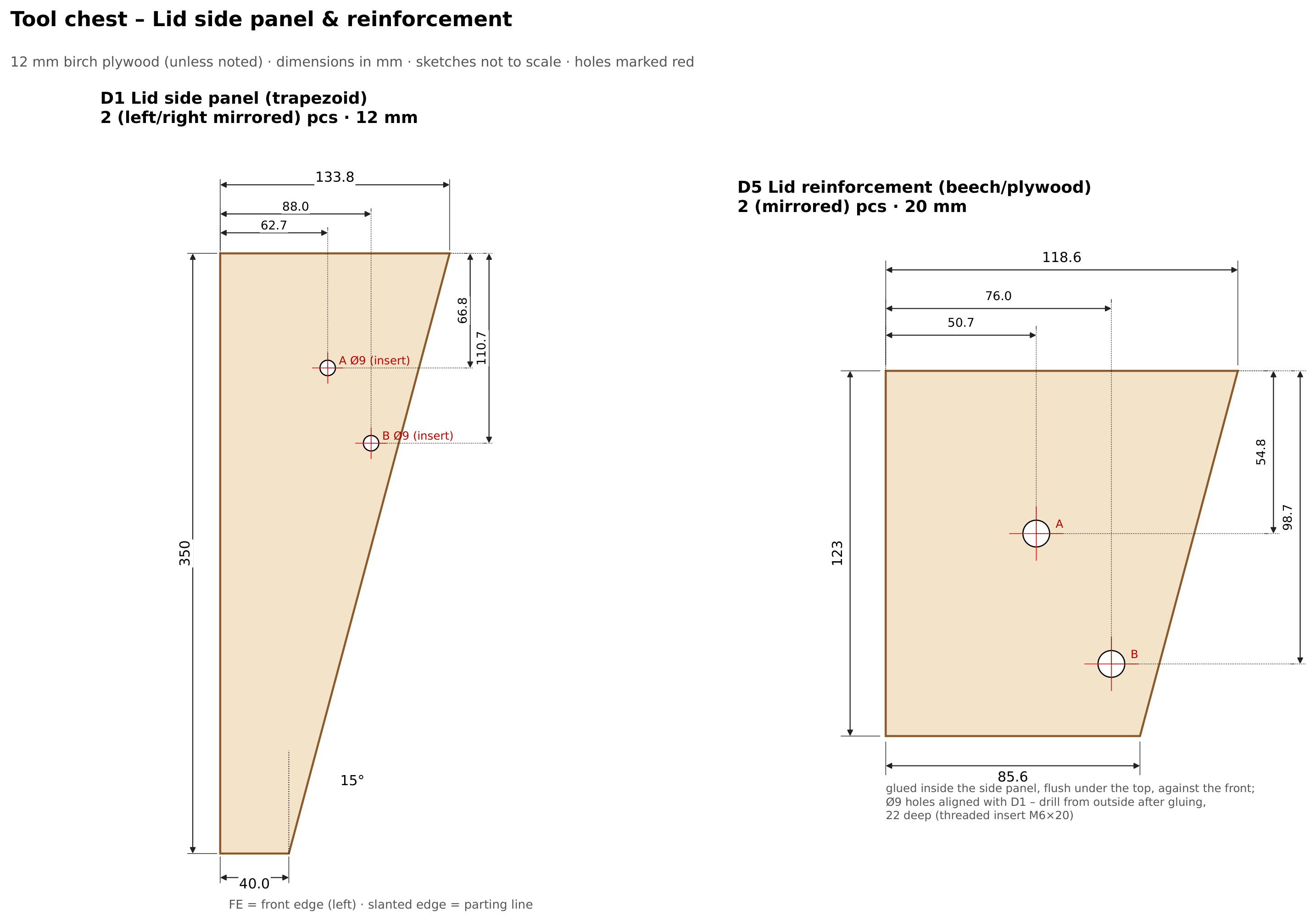
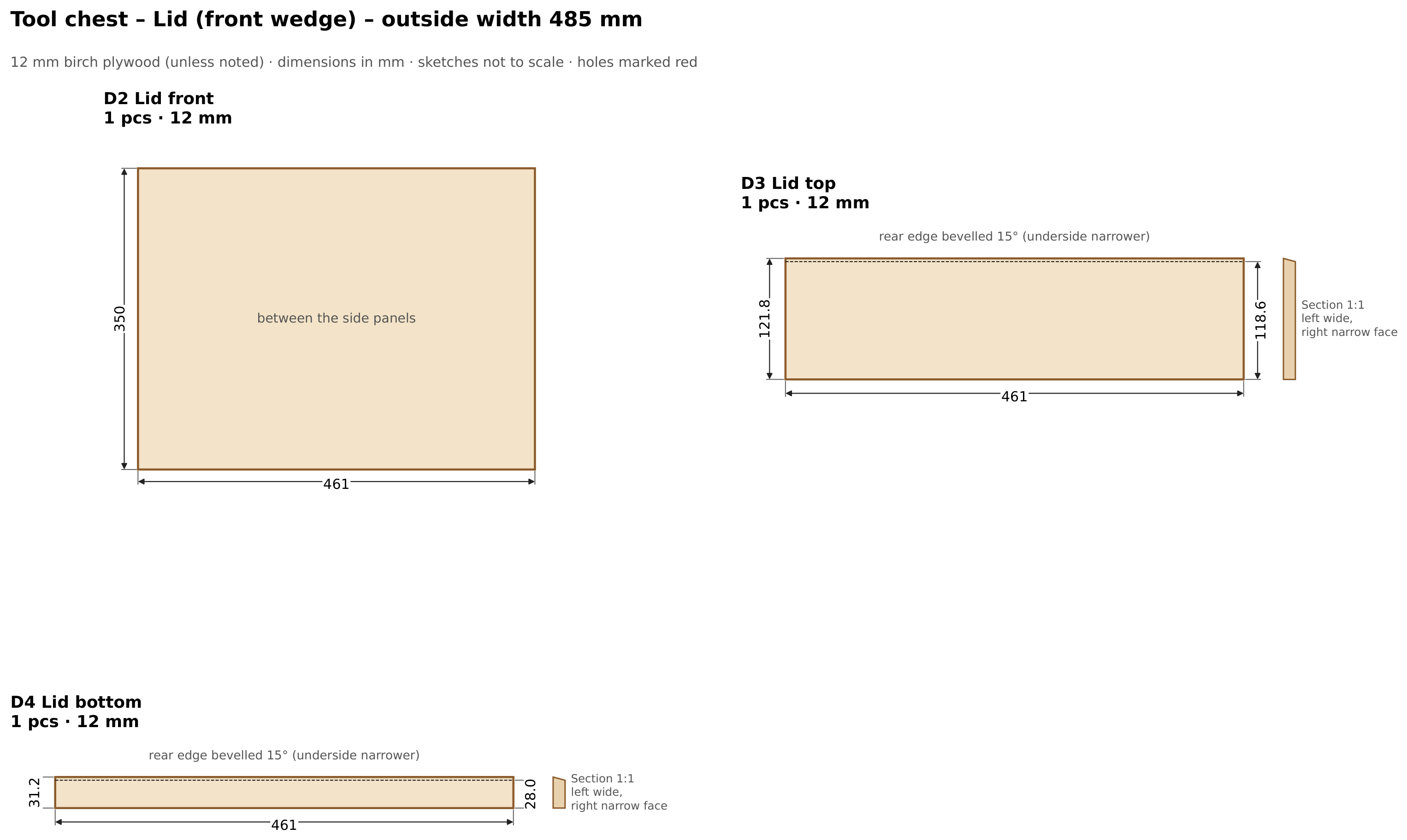
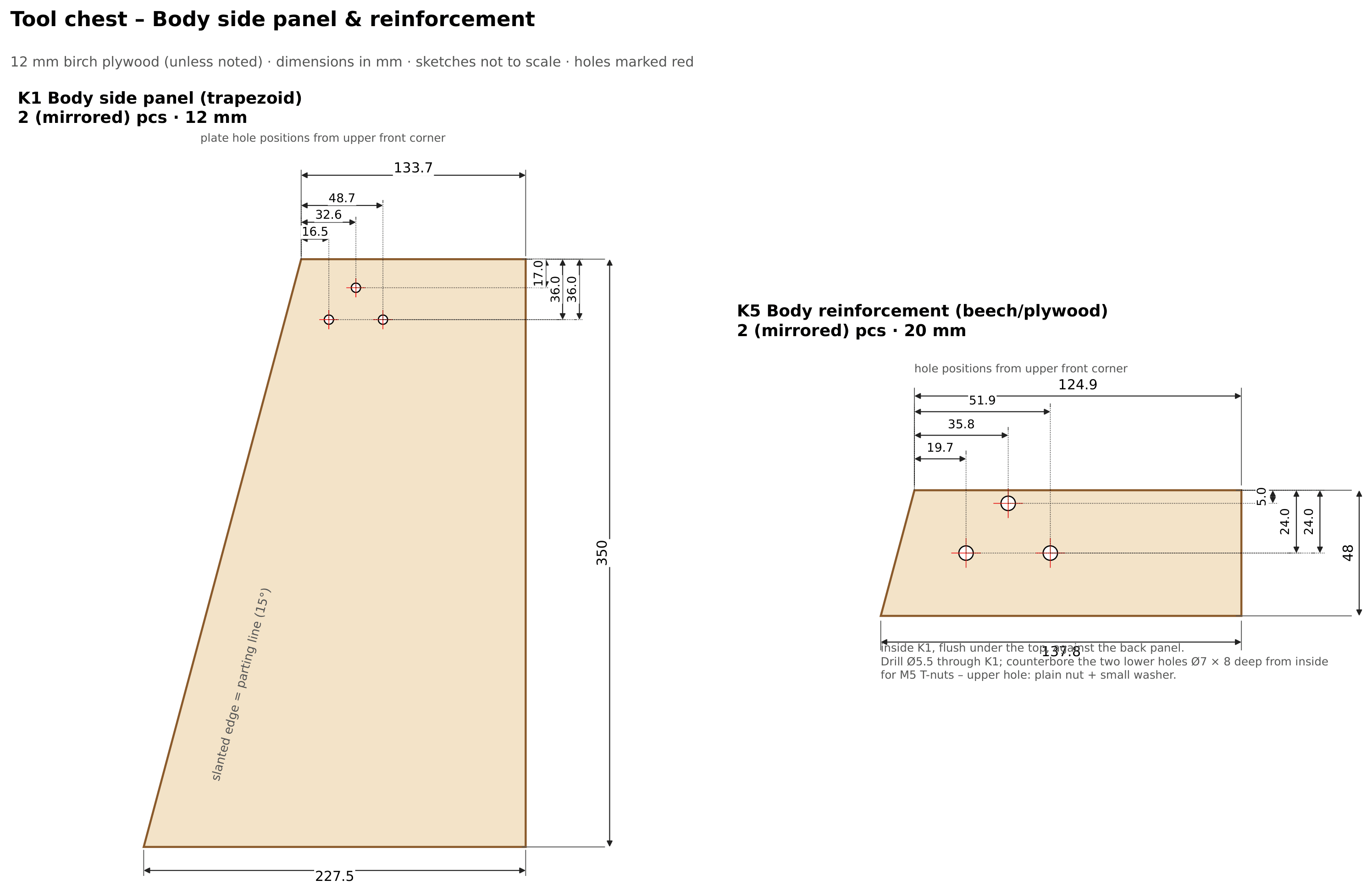
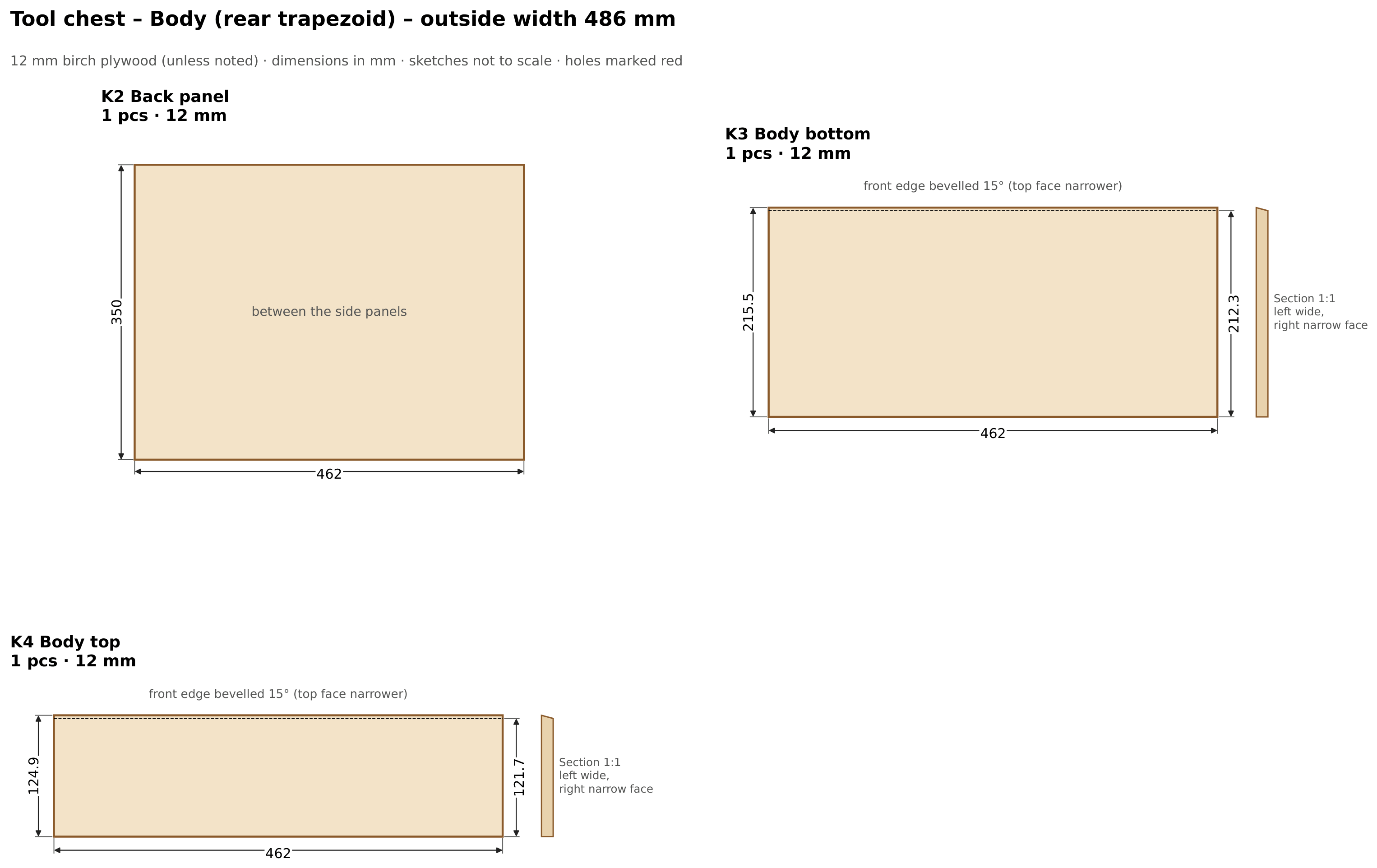
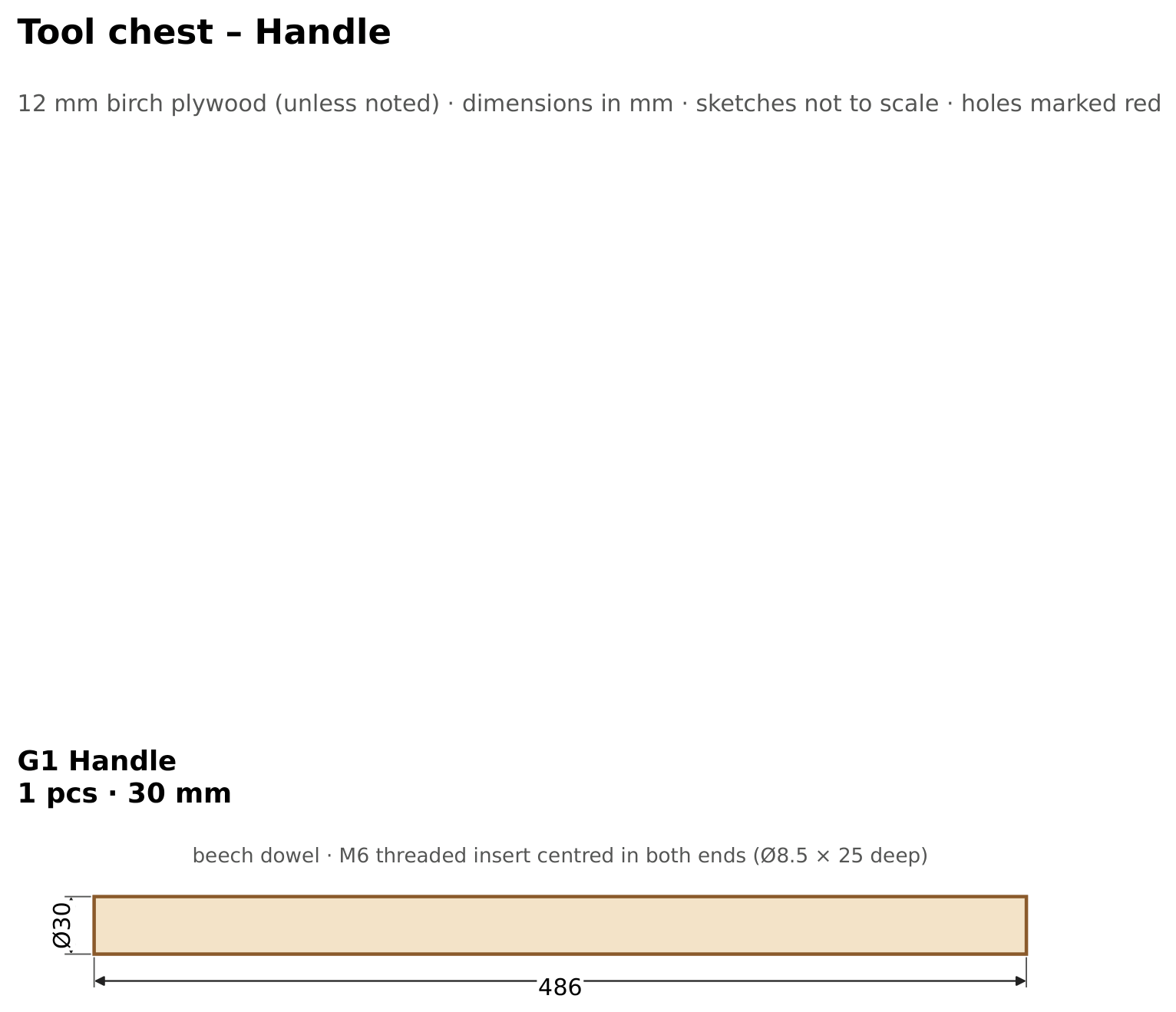
1:1 templates (PDF): the links, the handle plate (which doubles as a drilling jig), a drilling template for the lid pivots, and the cut list. Print at "Actual size / 100 %" and measure the 100 mm check bar before you use them.
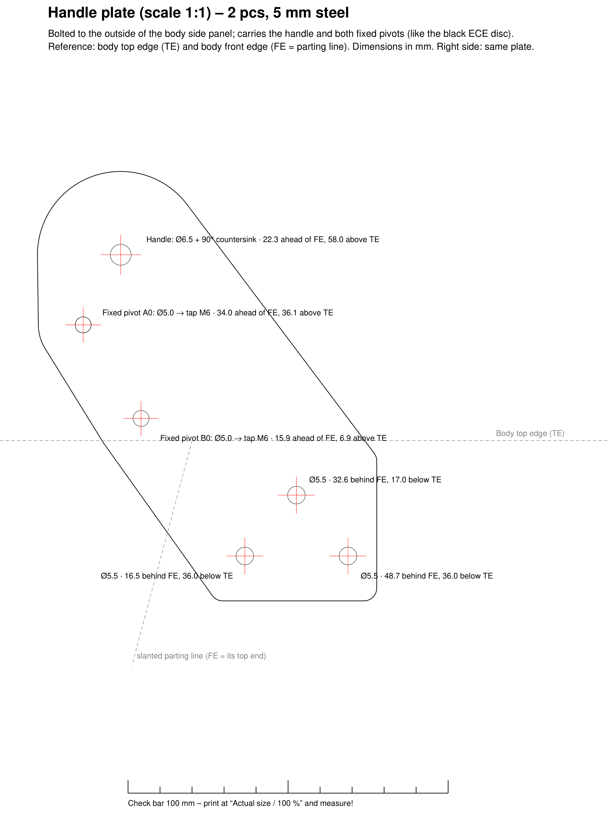
CAD (STEP), for example to open in Onshape or Fusion: Tool_chest_STEP.zip (closed, half open and open)
Two abbreviations used in the drawings:
- TE = top edge.
- FE = front edge. On the handle plate this is the top end of the slanted parting line on the body. On the lid template it is the lid's front face.
4. Build
4.1 Cutting
- Split the side-panel blanks diagonally (271 × 350 → D1 + K1). Mark the cut from 40.0 mm at the bottom to 133.8 mm at the top, measured from the front edge.
- Bevel the 15° edges of D3, D4, K3 and K4, working to the narrower dimension.
- Rip D4 to width and cut the slants of the reinforcements D5 and K5.
- Dry-fit everything and check that the slants of lid and body meet cleanly.
4.2 Joinery
Butt joints, glued and screwed. The side panels run through, and all other panels sit between them.
- Wood screws 3.5 × 30 go through the side panel into the panel edge, about every 100 mm and at least 20 mm from the ends.
- Pre-drill in two steps:
- Ø4 clearance hole through the side panel, then countersink. Fully threaded screws would otherwise grip both parts and not pull the joint tight.
- Ø2.5 pilot about 25–30 mm deep into the edge. Plywood edges split easily.
- Easiest way to keep the holes aligned: clamp the parts, drill Ø2.5 through both, then open up only the side panel to Ø4.
- Check the diagonals: equal length means square.
The body carries the whole load through the handle and plates, so build it sturdy. The lid carries almost nothing.
4.3 The body
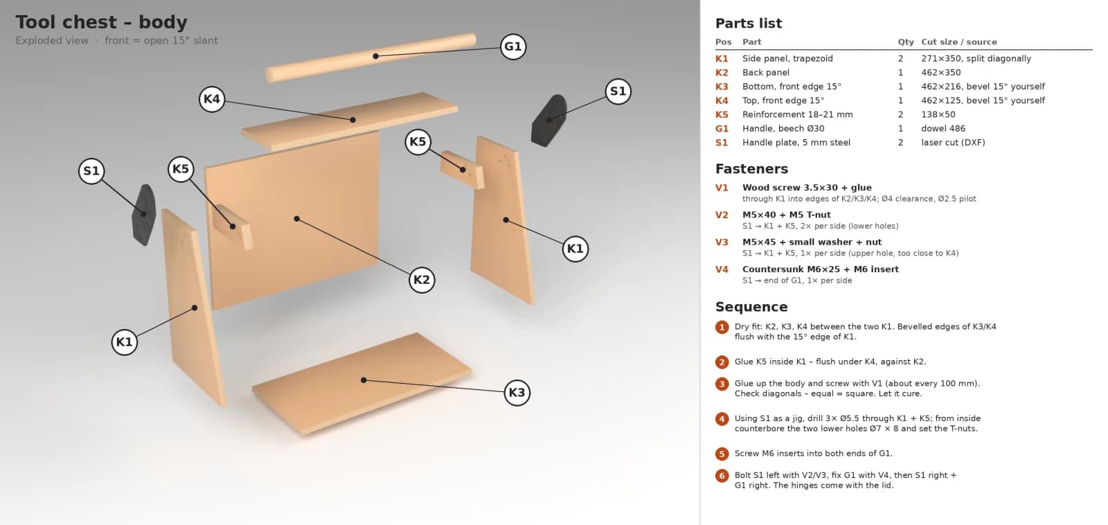
- Dry-fit K2, K3 and K4 between the two K1. The bevelled edges of K3 and K4 sit flush with the 15° edge of K1.
- Glue K5 inside K1, flush under K4 and against K2.
- Glue and screw the body. Check the diagonals and let it cure.
- The steel parts come next (4.4 and 4.5).
4.4 Preparing the steel parts
- Tap M6 in the fixed pivots A0 and B0 (Ø5.0 holes).
- Countersink the handle hole (Ø6.5, 90°) on the outside. Do the second plate from the opposite face, so you get a left and a right plate.
- Deburr. Paint or blacken now if you want to.
- If the links wobble on the shoulder screws, have the holes lasered at Ø7.8 and ream them to Ø8 H9.
4.5 Mounting the handle plates and the handle
Align the plate. It overhangs the body at the top and towards the front. Clamp it and check:
- A0: 34.0 ahead of FE, 36.1 above TE
- B0: 15.9 ahead of FE, 6.9 above TE
Both sides must be identical; otherwise the lid will run crooked.
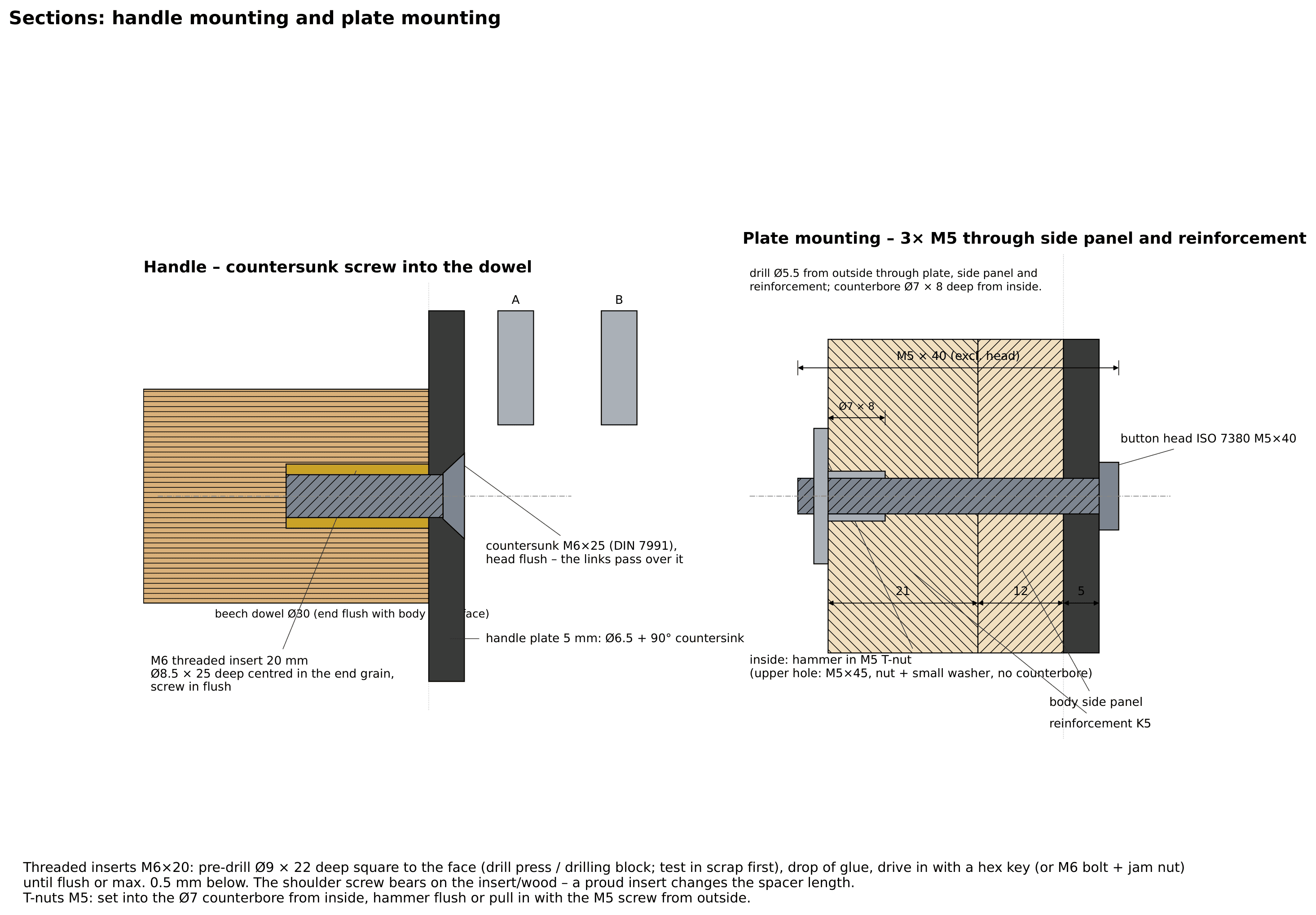
Drill Ø5.5 through the three plate holes, through K1 and K5. Back the exit side with scrap so the inside face stays clean. Drill one hole first, put a bolt in, then drill the other two.
From the inside, counterbore the two lower holes Ø7 × 8 deep and hammer in the M5 T-nuts.
The upper hole gets no T-nut. Its centre is only 5 mm below K4, and the 16–19 mm T-nut flange wouldn't fit. Use a plain nut there with a small washer (Ø9–10). A large fender washer won't fit either.
Handle: drill each end of the dowel dead centre, Ø8.5 × 25 mm deep, ideally on a drill press with a V-block. Drive in the M6 inserts with a drop of epoxy. Test the hole size in an offcut first, because end-grain beech is hard.
Bolt on the left plate, fix the handle with the M6 × 25 countersunk screw, then do the right plate and the right handle screw. Use low-profile button heads for the plate bolts.
4.6 The lid
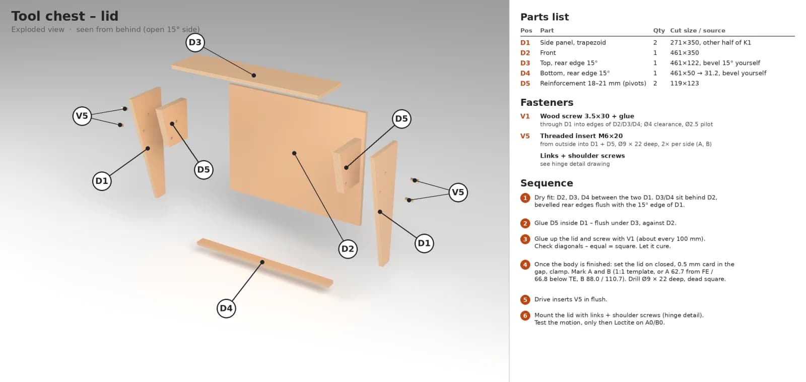
- Dry-fit D2, D3 and D4 between the two D1. D3 and D4 sit behind the front D2, with their bevelled rear edges flush with the 15° edge of D1.
- Glue D5 inside D1, flush under D3 and against D2.
- Glue and screw the lid, check the diagonals and let it cure.
4.7 Drilling the lid pivots in place
Drill the lid pivots only after the body is finished. That way they line up with what you actually built.
- Put the lid on the body in the closed position, with a 0.5 mm piece of card in the parting line, and clamp it.
- Mark A and B with the 1:1 template, or measure them:
- A: 62.7 from the lid front, 66.8 below the top
- B: 88.0 from the lid front, 110.7 below the top
- Drill Ø9 × 22 mm deep, perfectly square to the face, through D1 into D5. Use a drill press or a drilling guide.
- Drive the M6 × 20 inserts in flush, or at most 0.5 mm below the surface. A proud insert changes the spacer length.
4.8 Assembling the hinge
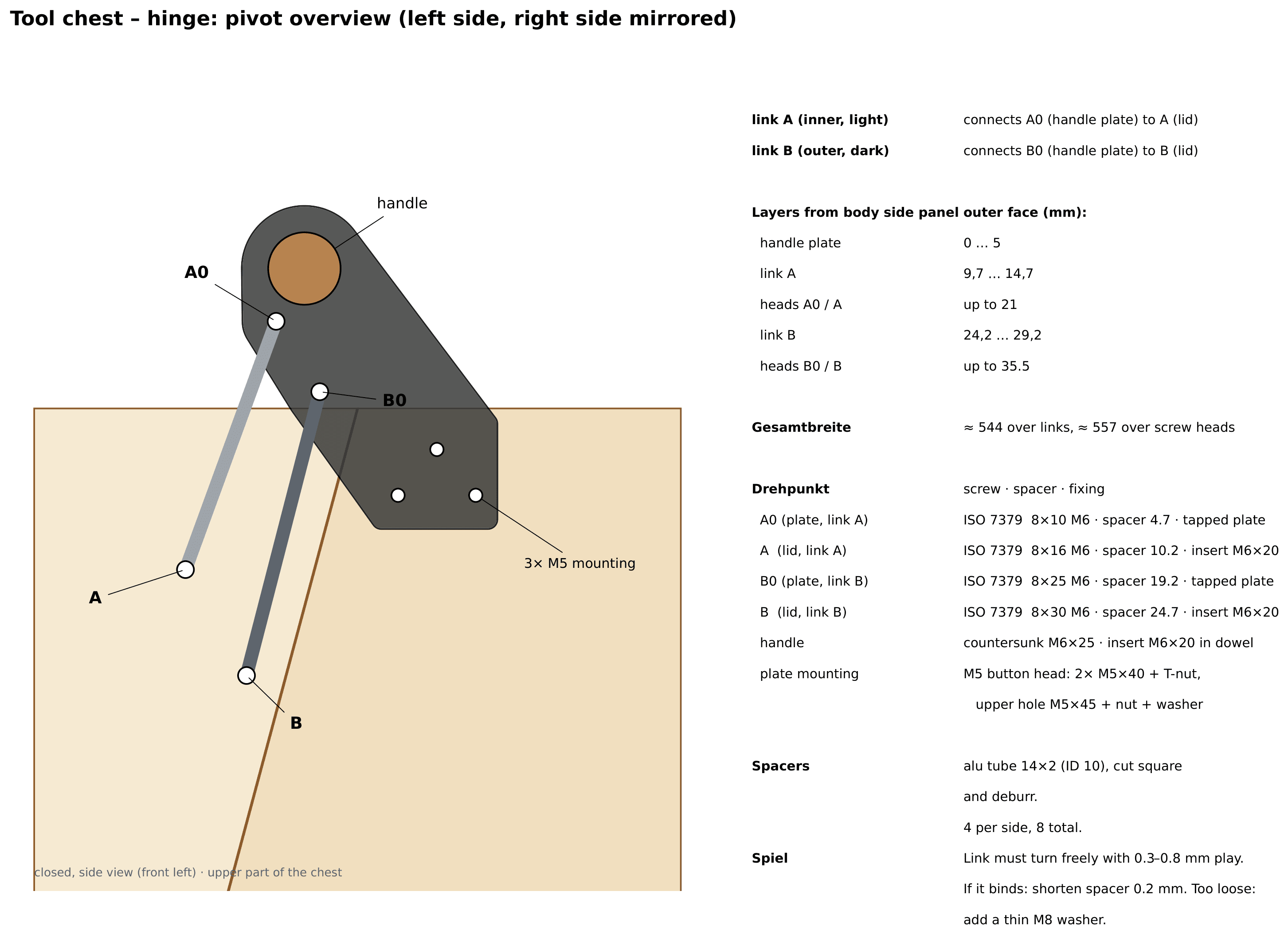
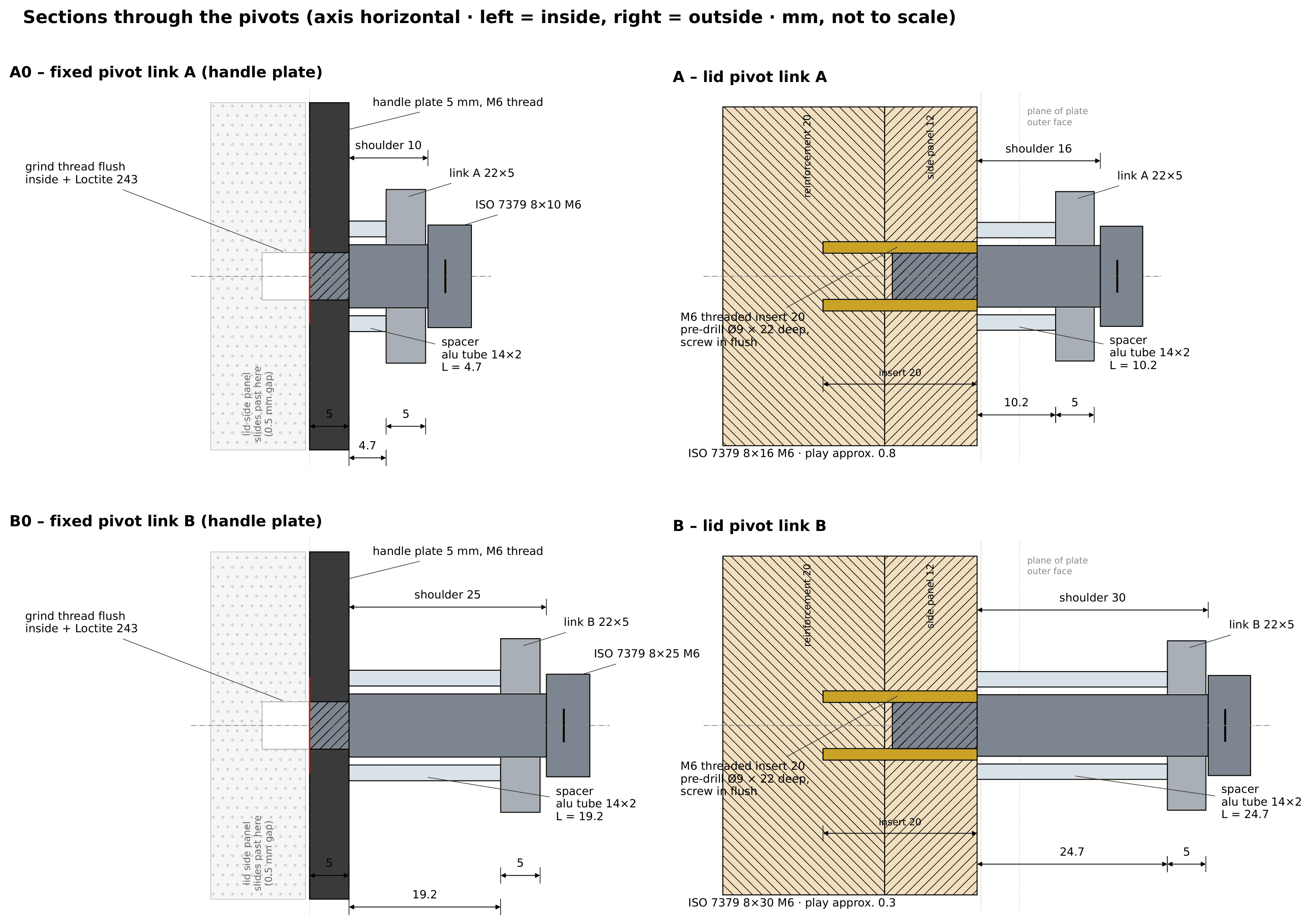
| Pivot | Shoulder screw | Spacer (tube 14 × 2) | Fixed into |
|---|---|---|---|
| A0 (plate, link A) | ISO 7379-8-M6-10 | 4.7 mm | tapped plate, Loctite 243 |
| B0 (plate, link B) | ISO 7379-8-M6-25 | 19.2 mm | tapped plate, Loctite 243 |
| A (lid, link A) | ISO 7379-8-M6-16 | 10.2 mm | M6 insert |
| B (lid, link B) | ISO 7379-8-M6-30 | 24.7 mm | M6 insert |
Make two of each, one set per side.
- The link turns on the screw's ground shoulder, and the screw clamps on its shoulder, so nothing binds.
- Each link needs 0.3–0.8 mm of play. If it binds, shorten the spacer by 0.2 mm. If there's too much play, add a thin M8 washer.
- ⚠️ Grind the thread of A0 and B0 flush on the inside of the plate. The lid's side panel slides past only 0.5 mm behind it.
- Cycle the lid slowly by hand. Apply Loctite to A0 and B0 only once everything runs smoothly.
Downloads
- Dimensioned wood parts: Wood_parts_dimensioned_EN.pdf
- 1:1 templates and cut list: Templates_1to1_EN.pdf
- Hinge detail drawing: Hinge_detail_EN.pdf
- Laser DXF (5 mm steel): handle plate · link A · link B · all parts
- Hinge simulator (Python): hinge_sim.py
- CAD (STEP): Tool_chest_STEP.zip (closed, half open and open)
Credits
- The original design is the ECE Montagebox by E.C. Emmerich. This is an independent reconstruction, not affiliated with ECE.
Comments
Loading comments…